The center of energy-saving solutions!
Products

Optimum Power Control Device For Motors
(OPC-M)
It is an AI-type motor power saving device that reduces effective power by 15~50% while maintaining a power factor of 0.98 or more at all times by tracking and controlling the optimal point of operation of the drive motor when operating facilities such as fans, blowers, pumps, compressors, various presses, hydraulics, and pump-jacks of onshore oil wells, and has obtained a certificate of designation as an energy innovation product from the Ministry of Trade, Industry and Energy in 2022, and is registered for procurement on the Korea Public Procurement Service.
Optimum Power Control Device For Motors
(OPC-M)
Optimum Power Control Device For Motors : OPC · M
When designing an initial production line at an industrial site, it is common to install the capacity of the induction motor applied to the facility with a spare capacity compared to the actual capacity in order to ensure stable operation of production, and in some cases, the capacity is further expanded as a matter of policy in consideration of the uncertainty of future production.
If the actual production line is operated with more spare capacity than necessary, a lot of power losses are continuously generated due to decreased efficiency, and if only enough active power is supplied to produce the same or slightly more shaft power than the required shaft load, production efficiency can be improved and power costs can be reduced.
Optimum Power Control Device For Motors (OPC-M) is a motor power load optimization control device that continuously/repeatedly detects the actual current that is varied in proportion to the axial load taken in real time during motor operation at a rate of 1 in 100,000 through a current transformer (CT), In response to this, the OPC-M Kit calculates the current power consumption and calculates the rotational speed of the motor that can optimally exert that power according to the power law, and then selects a signal (4~20mA) that can realize that rotational speed and sends it to the inverter (VFD), and according to the signal, the inverter modulates the basic frequency (50Hz or 60Hz) of the motor, and the motor is controlled and operated at that rotational speed.
This control limits more current from entering the motor than necessary to keep the motor efficiency consistently above 0.98, and by running this control continuously/repetitively, the active power consumed by the motor is reduced by 15-50%.

OPC-M Control Diagrams and Schematic [Hydraulic/Pneumatic Equip]

Examples of losses in pump operation
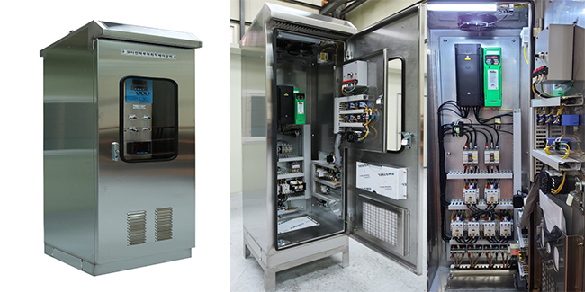
Optimum Power Control Device For Motors (OPC-M)
Key Components
- Current Transformer : Detects the incoming current, which fluctuates in real time
- OPC-M Kit : : Recognizes the actual load through the detected current value, calculates the appropriate motor speed, and transmits the corresponding signal (4~20mA) to the inverter
- Inverter(VFD) : Controls the motor speed by generating a frequency that matches the corresponding signal (4~20mA) transmitted from the OPC-M Kit
- Noise Filter / AC Reactor : Eliminates and minimizes harmonics affecting the device
Major Applied Facilities
- Fans / Blowers / Pumps / Compressors / Various presses / Injection machines / Pump-Jacks in onshore oil wells
Applicable Induction Motor Main Power
- AC3 phase 220V / 380V / 440V / 3300V / 6600V
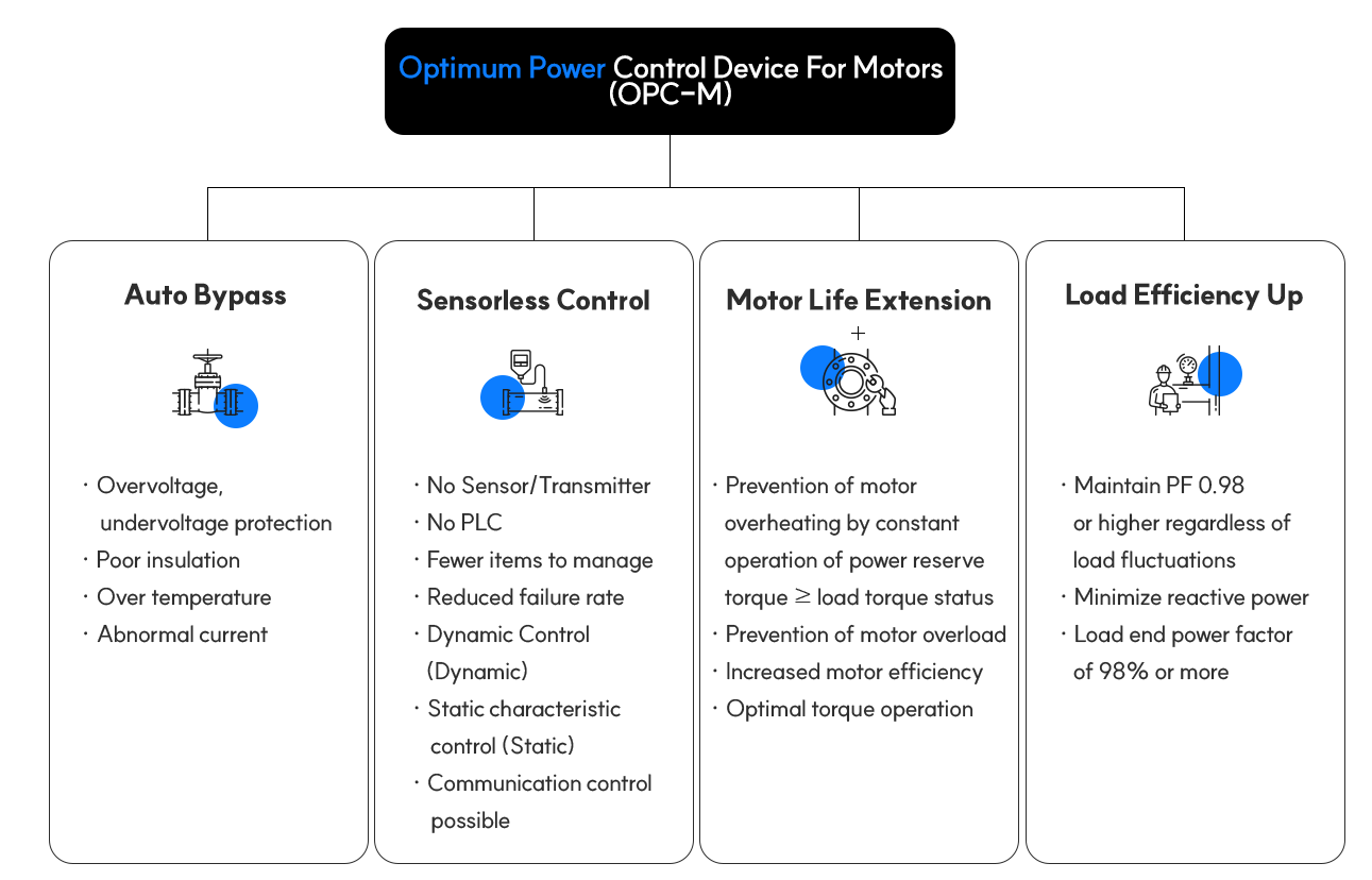
Core Functions of the Optimum Power Control Device For Motors
Estimated Power Savings by Device
좌우로 스크롤 하시면
내용이 보입니다.
| Applicable Load | Behavioral Concepts | Power Savings Prediction [%] |
|---|---|---|
| Hydraulics and Injection Airflow | Sensorless auto P (proportional) + I (integral) + D (differential) control of load torque for each of the seven stages of the process saves electricity without compromising quality and production. | ≥20 |
| Press Type | Sensorless Auto P (proportional) + D (differential) control by detecting the load torque in the state of pressing and lifting and applying only sensorless auto P (proportional) + D (differential) control is applied to presses with long unloading states. | 15~20 |
| Compression Type | Sensorless Auto P.I.D. control method detects the compression ratio of loading and unloading and applies P (proportional) + D (differential) control and P (proportional) + D (differential) + I (integral) control when loading, i.e., constant pressure, quantitative, and precise control modes. | 15~50 |
| Fan/Blower type | Smart control system is built by environmental memory method that detects the amount of difference force of ID or FD capacity and applies only sensorless auto P(proportional) + I(integral) control | ≥30 |
| Pump Type | Establishment of a smart control system with environmental memory by sensorless auto P+D control, P+I control, P+I+D control, and P+I+D control that automatically varies the speed and torque as the suction and discharge increase and decrease. | ≥25 |
| Pump Jack(Grasshopper) | Sensorless Auto P,I,D control method by detecting the load torque at each stage of the up stroke and down stroke cycle process to create a double effect of increasing production and saving electric energy | ≥20 |
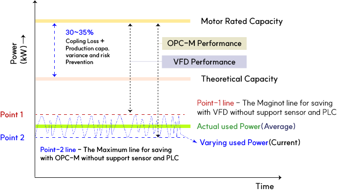
Comparison of operating characteristics of OPC-M and inverters
- The actual power required to run an electric motor is constantly changing between the peak Point-1 and the trough Point-2 as shown in the figure. Even if there is no intentional change in production conditions, it is bound to change continuously due to the many requirements connected to the motor.
- When utilizing VFDs for conservation control, you may want to control the operation by locking Point-1 at a specific point for stable production operation. If you also want to control the lowest point of Point-2, you need additional means (Sensor + PLC) to generate and control signals that define the value and timing of the two points, and it may be difficult to control if the fluctuation factors of the power are unplanned and unclear.
- In the case of OPC-M, on the other hand, it is possible to control by following the change pattern within the area of Point-1 and Point-2 continuously using the change value of the current change through the current transformer without the use of general sensors, so an additional power saving of 5~10% is possible compared to VFD control.
The difference between OPC-M and inverter (VFD) control and the benefits of OPC-M
| Inverter (VFD) | OPC-M | OPC-M Benefit | |
|---|---|---|---|
| Main functions | Motor speed control through frequency adjustment to achieve one or multiple set target speeds. | Select the optimal motor speed through continuous PID operation to limit the current to only the amount suitable for the real-time changing shaft load, and control the motor speed using an inverter. | Superior power savings through continuous motor speed control optimized for shaft loads (15 to 50% or more savings) |
| Main purpose | To control the rotational speed of a motor for intentional/continuous operation. | Control the rotational speed of continuous motor | |
| Control method and means |
|
|
|
| Sensing | Various sensors + signal conversion transducers | Actual current consumption detection using current transformer (CT) | Significantly lower malfunctions |
| Field Management | PLC programmer and maintenance specialist are always needed | General field workers can be managed | Cost saving/manageability |
| Investment | Additional investment required for PLC, sensor, and transducer for automatic operation management | Full functionality including all inverters within the OPC-M device (also includes Noise Filter and AC Reactor for harmonic reduction) | Same level of investment compared to inverter but high savings enables fast PB |
A field-ready derivative of the Optimum Power Control Device For Motors(OPC-M)
The basic OPC-M should be configured as a 1-motor 1-OPC-M, but the following derivatives can be applied depending on the characteristics of the field equipment
C.O.S (Change of Selector Switch) Type OPC-M
When there are two motors installed in the load facility for the same purpose, but only one motor is always in operation, it is possible to install only one C.O.S type OPC-M instead of installing one OPC-M for each motor, so that when #A motor is running, OPC-M is switched to #A and operated, and when #B motor is running, OPC-M is switched to #B and operated. Also, if #B Motor is started while OPC-M is being used as #A, #B Motor can be operated as Bypass
The main effect is that it takes up less space by not installing one OPC-M for each motor, and it is more economical than installing two OPC-Ms, and the facility can be operated more efficiently by switching the OPC-M to A when the #A motor is running and switching the OPC-M to B when the #B motor is running. If there is an inverter error inside the OPC-M, both #A and #B motors can be operated as bypass, and if an inverter error occurs while operating in OPC-M mode, it will automatically switch to bypass.
DC signal (4-20 mA) distribution Type OPC-M
It is applied to facilities to control multiple load facilities for the same purpose at the same frequency, and the main effect is that it is more economical than installing multiple OPC-M kits because it is possible to control multiple facilities at the same frequency with one OPC-M kit using a 4~20mA Converter DC signal converter instead of installing one OPC-M kit each, and it is possible to operate facilities more efficiently because it is possible to control multiple facilities equally with one OPC-M kit. In addition, it is easy to control peak power by controlling multiple facilities simultaneously with a single demand signal for loads (fans, blowers) that are not directly related to production.